Camera Trap

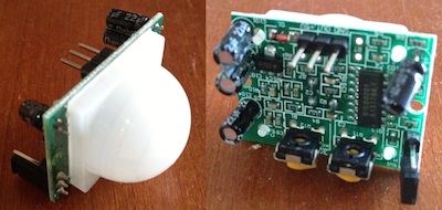
This page is about getting the Raspberry Pi camera module working and also using the General Purpose Input Output (GPIO) pins on the Raspberry Pi to recieve input from peripherals. If you don’t have the camera module you could use a USB webcam; my first camera trap used a PS2 EyeToy bought on eBay for £2.04 including shipping! I used a HC-SR501 Adjust IR Pyroelectric Infrared PIR Motion Sensor Detector Module, bought on ebay for £1.54 (shipping included) and sent slowly from Hong Kong, as the trigger.
The camera module
The first thing is to attach the camera module correctly, instructions are here, and that the camera is enabled (type ‘sudo raspi-config’ at the command prompt to check). You can then test that it will take photos by typing:
raspistill -w 1024 -h 600 -o image.jpg
at the command line. There are numerous options, which can be found in this instruction document. E.g.
raspistill -hf -t 4000000 -tl 1000 -w 1024 -h 600 -o /home/pi/Timelapse/image_%05d.jpg
ffmpeg -r 15 -i image_%05d.jpg -vcodec copy -r 30 out.avi
Here 15 is the fps of the input, 30 is the fps of the output. If you don’t already have it, you will have to install ffmpeg first (sudo apt-get install ffmpeg).
Here is an example timelapse movie taken during a DUMake hackday at Durham University at which ARM kindly provided us with lots of Raspberry Pis and other kit to play with.
The camera module can also take videos with the command
raspivid -o video.h264
You can view them on the Raspberry Pi (if you have it pllugged into a monitor, not if you are remotely accessing it) with the command line command ‘omxplayer video.h264’
However the output files are raw h264 and need to be converted before they can be easily viewed in normal video viewing programs. I use ffmpeg again, and the command:
ffmpeg -r 30 -i video.h264 -vcodec copy video.mp4
Then copy the video files to my laptop for viewing.
For a USB webcam you should be able to take a picture using the command:
fswebcam -r 640×480 image.jpg
but not all webcams work exactly the same way to you may have to experiment or research which work on the Raspberry Pi yourself. Again you may well need to install the right utility first (e.g. “sudo apt-get install fswebcam”).
Program camera control
Next you must be able to trigger the camera from your program. There are a few options here.
- The simplest is to execute a shell command (i.e. as above) from within python. This is done by using the ‘os’ module, so first we have a line to import that module, and then use the function os.system to pass a command to the system:
import os
os.system(“raspistill -w 1024 -h 600 -o image.jpg”) - A usually more convenient option is to install a python module that will give you native python commands for controlling the camera. I have found picamera to be good and well documented. At the command line install with “sudo apt-get install python-picamera” then within python you can capture images to file, stream or image objects.
- The last option I have used, which is my preferred option now, is to install a v4l2 (video for Linux) driver for the Raspberry Pi camera, which enables it to work with many existing Linux utilities easily. This is in the latest firmware, so after a ‘sudo rpi-update’ you should be able to activate it by typing
sudo modprobe bcm2835-v4l2
after which you can access the Raspberry Pi camera in any software using the v4l2 framework. If you have issues, try installing v4l-utils with ‘sudo apt-get install v4l-utils’, and try again.
GPIO pins
The GPIO pins are the bank of 26 pins in two rows of 13 near one corner of the Rapsberry Pi and next to the yellow video out socket. These pins can either be set to a high or low voltage by the Raspberry Pi (output), or the voltage supplied to the pin by some external peripheral can be read by the raspberry pi. However it is worth noting that supplying the wrong voltage to the pins, or connecting the wrong pairs of pins can permanently damage the Raspberry Pi.
To control the pins from python, you need to import the GPIO library, so add the line:
import RPi.GPIO as GPIO
to the top of your python program. You will also need extra permissions to run all your programs, i.e. open a command window and type ‘sudo python program.py’ to run the program program.py. Running it from within IDLE won’t work.
Confusingly there are two different numbering systems for referring to the pins on the Pi. I will use the board numbering, but other websites you may see could be using ‘BCM numbering’, see this tutorial for more info. So the first thing I need to do is set up the program to use the numbering system of my choice, by adding the line:
GPIO.setmode(GPIO.BOARD)
to the python program.
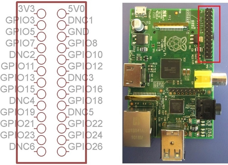
Of the 26 pins in the GPIO pin set, three pins are set to 3v, 5v and ground, and some are DNC (Do Not Connect) pins, but there remain seventeen that we can use.
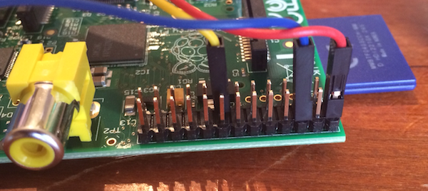
The PIR sensor I am using needs to be connected to power pins (5v and ground) and one additional pin through which it indicates its state. It sets this pin to 3v when it detects motion, and ground voltage otherwise. So I used the 5v (red) and ground (blue) pins, and one of the remaining pins; I chose pin 15 (yellow).
Each pin can be set up either to be an input (some peripheral sets to voltage and the Raspberry Pi reads its value) or an output (the Raspberry Pi sets the voltage and the peripheral reads the value). We need an input, so add line
GPIO.setup(15,GPIO.IN, pull_up_down=GPIO.PUD_DOWN)
which sets pin 15 to be an input and ‘pulls it down’ to ground if it is not being actively set by the peripheral. This stops the value floating about and causing trouble.
We can now use the pins! The variable GPIO.input(15) takes value 1 if pin 15 is at 3v and value 0 otherwise, so we can use a condition statement such as ‘if(GPIO.input(15))’ to take action dependent on the value of the pin. The simple program PIR_test.py checks the value of the pin every second and prints out the result. After 20 seconds it stops and informs the Raspberry Pi that it is no longer using the GPIO pins (so that other programs could get access to them) with the line:
GPIO.cleanup()
Putting it together
Checking the pin value repeatedly is called polling. It is not always the best way of doing things, and can waste a lot of time checking for events that may not happen often. We would rather have a function that was triggered by the pin value changing, instead of having to check all the time. Using the line:
GPIO.wait_for_edge(15,GPIO.RISING)
will effectively pause the program until the pin’s value rises (from ground to 5v). So if we put this in a loop, as below, with a photo being taken, it will take photos on the first ten occasions that the PIR detector is triggered.
for i in range(10):
GPIO.wait_for_edge(15,GPIO.RISING)
os.system(“raspistill -o /home/pi/Desktop/image”+str(i)”.jpg”)
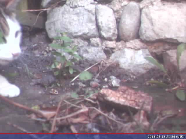
In my final code for the camera trap I put the photo taking part in a function that was called on each trigger of the PIR sensor, and had it first take a 5 second video, then keep taking photos while the PIR sensor was still high. It puts the images in a folder Webcam. To stop this filling up indefinitely, the program clears out the folder at the beginning of each run, so between running the program I have to go ing and copy any images I want to keep. Here is the code: Camera_trap.py.
It may not be the most impressive results, in part because I was using a crummy webcam rather than the camera module, but these show it works!
 | 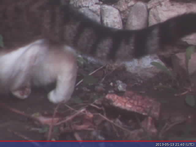 |
Run on boot
In order to get the camera trap to ‘just work’, I set it so that the python program would run immediately after the Raspberry Pi boots. Then I could take the trap into the garden, plug in the battery and it would launch itself with no keyboard or interaction from me. I arranged the autolaunch by adding the line
sudo python /home/pi/Webcam/Camera_trap.py &
to file /etc/rc.local just above the last line (exit 0). You can launch the editor by typing ‘sudo nano /etc/rc.local’ at the command line. You must then reset permissions at the command prompt with
sudo chmod 755 /etc/rc.local
the script should now run and photo the first 100 things to go by.
Upload images to Dropbox
Once you have it all working, if your Raspberry Pi is in range of wifi you can have a go at getting it to load the images straight into a Dropbox folder. At one stage I got this Raspberry Pi – Dropbox Uploader working, although now I just whip out the SD card and pull the images off it onto my laptop.

Raspberry Pi is a trademark of the Raspberry Pi Foundation